WIND GENERATOR OPERATION |
|||||||
<---------------------------------------------------------------------------------------------------------------------------------> |
|||||||
THE TYPESThere are two main categories of wind systems: constant speed and variable speed. A constant speed induction generator can be connected directly to the grid if it uses a proper grid-tie inverter. The angular velocity of its rotor is controlled by the pitch of the turbine blades. A gear box then raises the RPM to yield 50 or 60 Hz output. Such design is used primarily in high-power utility-scale systems. Variable speed systems use synchronous generators that produce unregulated AC voltage. CHARGERFor a small hobbyist system one can connect the turbine through a rectifier directly to a battery. This is the simplest approach, although it is also the least efficient as we will see below. This schematic shows a design idea for such a wind-powered charger. |
|
||||||
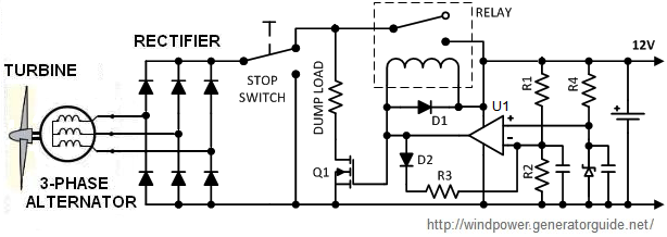 Here is how it works. The battery "clamps" the alternator voltage. The opamp monitors it via the divider R1, R2 and compares to a reference. Under normal conditions opamp U1 stays low, the relay is energized and Q1 is OFF. When the battery is fully charged and its voltage is approaching maximum permitted value, U1 switches to "high" state, the relay opens and terminates the charge. At the same time Q1 turns ON and connects the turbine to a dump load. D2 and R3 provide a hysteresis to avoid a hiccup mode: when opamp is high, it increases the voltage at R1-R2 junction. As the result, the battery has to discharge to a certain level before it will be connected back to the turbine. D3 should be a temperature compensated precision reference, such as LM4040-2.5. For a 12V battery with 14V maximum charging voltage we can set for example R1=11.3k, R2=2.5k. This will provide 13.8V cut off. With R3=54k the relay will activate again when the battery discharges to approximately 12V (you may need to trim R3 for a desired threshold). Examples of other parts: Q1=STP80N70, D1,D2=1N4819, U1=LM6132 (it should have rail-rail output), R4=10k. The relay should be automotive type such as G8JN-1C7T-D-DC12.
 REGULATORS
In the above circuit, available energy in the wind will often be lost. Also, the battery can easily be damaged because its rated charge voltage varies with the temperature. A much better approach is to use a PWM regulator, such as the one shown on this block diagram.

The rectifier bridge produces pulsating DC voltage- see the waveforms of an ideal 3-phase rectification. The resulting output is shown in red. Theoretically, with a resistive load the ripple are just 4.2% without any capacitors.
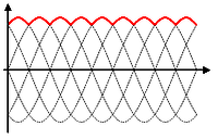 In reality, of course, the alternator does not deliver a clean sinewave, especially because winds usually blow in gusts. Nevertheless, output ripple here are quite low even without any smoothing filter.
The switching regulator in this example is so-called SEPIC converter. Its main advantage is its output can be greater than, less than, or equal to the input. Therefore it can provide a charge in a wide range of winds. When Q1 is on, energy is being accumulated in L1. At the same time the coupling capacitor "C" transfers energy to L2. When Q1 turns off, L1 current continues to flow through "C" and the diode to the load. For a steady state operation in a continuous conduction mode, output is given by Vout=Vin×D/(1-D), where D-duty cycle of the switching MOSFET. You can see that for D=0.5 Vout=Vin, for D<0.5 Vout<Vin, for D>0.5 Vout>Vin. You can find more info on the operation of power electronics converters in smps.us site. Note two additional protection components in the above diagram. A solid state switch Q2 automatically connects "dump load" when turbine's output reaches dangerous levels. An optional manual "stop switch" disconnects regulator and shorts all alternator coils. Mechanical breaking however is more reliable.
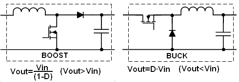 The main disadvantage of SEPIC is the coupling capacitor "C" has to pass an entire load current. This makes this topology best suited to low-power applications. For mid-power wind generators "boost" and "buck" converters may be more suitable. Here are their basic conceptual diagrams. In boost converter output is always greater than input: Vout=Vin/(1-D). This topology is used when you want high DC-link (up to several hundreds volts). If DC-link is above peak of the desired sinewave, it can be fed directly into a transformerless inverter. For 115VAC this value would be around 200VDC. Conversely, buck is suitable for low-voltage designs, such as 12VDC, when the turbine output is normally higher than the battery voltage.
All information in this site is provided AS IS without guarantee or liability of any type, neither explicit or implicit- see complete Disclaimer linked below.
<--------------------------------------------------------------------------------------------------------------------------------->